Hydroelectric Power Plant Control System
A hydroelectric power plant control system using Siemens TIA Portal, featuring sequence-driven operation, real-time process control, alarm handling, and HMI-based system interaction.
Navigate this project
Project Overview
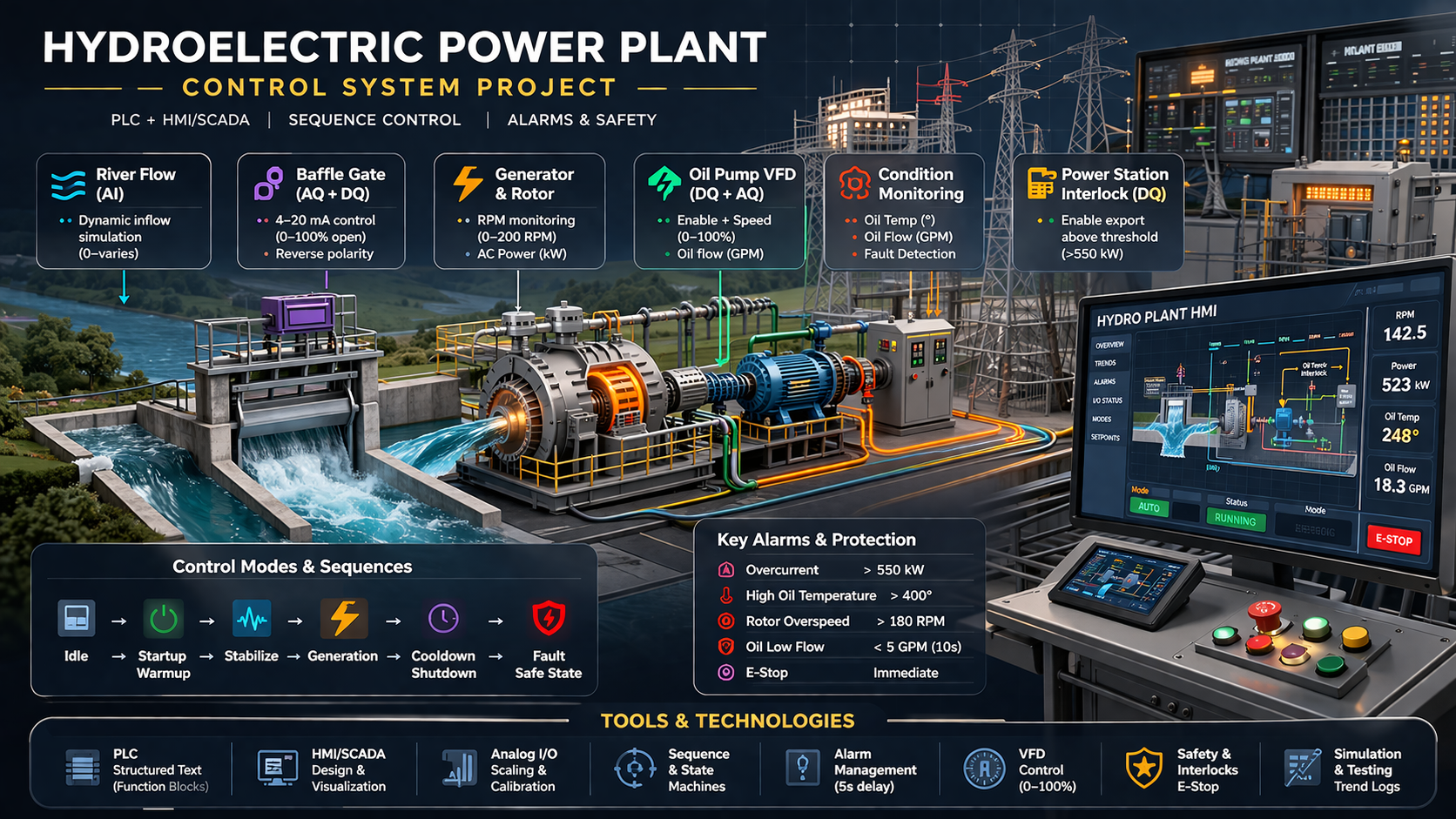
This project focuses on the design and implementation of a hydroelectric power plant control system using Siemens TIA Portal. The system simulates a real-world industrial process where water flow is used to drive a turbine, generating electrical power while maintaining safe and stable operation.
The plant operates on a dynamically changing river flow, which is controlled using a baffle mechanism driven by an analog output signal. The controlled flow drives a turbine rotor, where rotational speed directly affects power generation. As the system operates, additional subsystems such as oil cooling, generator braking, and interlocks are actively managed to ensure safe performance.
The control system is responsible for coordinating multiple aspects of plant operation, including:
- Hydroelectric process simulation with realistic plant behavior.
- TIA Portal PLC logic for startup, run, shutdown, and fault states.
- HMI screens for operator control, feedback, and alarm visibility.
- Protection strategy including interlocks and braking conditions.
- Commissioning-oriented structure for validation and diagnostics.
The system is implemented using PLC-based control logic, with a strong focus on real-time decision making, process stability, and safety. An HMI interface is developed to provide operators with system visibility, manual control options, alarm management, and process monitoring.
This project reflects real-world industrial automation challenges, including analog signal scaling, sequence-based control, interlocks, and fault handling, making it representative of modern control systems used in power generation and process industries.
Engineering Objectives
The objective of this project is to design and implement a complete industrial control system for a hydroelectric power plant, focusing on safe, stable, and automated operation under varying process conditions.
The project aims to achieve the following:
- Develop PLC-based control logic to manage the full operational lifecycle of the plant, including startup, generation, cooldown, and shutdown sequences.
- Implement sequence-driven control using structured state logic to ensure deterministic and repeatable system behaviour.
- Design and integrate analog I/O processing, including signal scaling, calibration, and interpretation of real-time process variables.
- Control actuator systems such as the baffle mechanism and oil pump using digital and analog outputs, including VFD-based speed control.
- Implement comprehensive alarm handling and safety logic, including fault detection, delayed alarms, and defined shutdown responses.
- Develop an operator-facing HMI system for monitoring, control, and alarm management, ensuring clear system visibility and usability.
- Ensure safe operation through interlocks, emergency stop handling, and controlled system transitions during normal and fault conditions.
- Simulate real-world industrial scenarios including fluctuating inputs, equipment constraints, and process limitations.
- Apply structured testing and debugging methods to validate system performance and reliability.
System Architecture
The hydroelectric power plant is structured as a closed-loop industrial control system in which the PLC continuously monitors field inputs, evaluates operating conditions, and adjusts outputs to maintain safe and stable generation. The process begins with varying river flow entering the plant, where a baffle actuator regulates the amount of water passing through the turbine-generator assembly.
As water flow increases, rotor speed rises and electrical generation increases accordingly. To support operation, an oil pump driven through a VFD supplies lubrication and cooling to the rotor bearings. The PLC monitors oil flow, oil temperature, rotor speed, and generated power, then coordinates control actions such as baffle positioning, pump enable and speed control, brake engagement, station interlock status, and alarm response.
Key Inputs to the PLC
- Rotor speed feedback (RPM)
- Oil flow measurement (GPM)
- Oil temperature feedback
- Generated power / current feedback (kW)
- E-Stop status
Key Outputs from the PLC
- Baffle enable and analog position control
- Oil pump VFD enable and speed reference
- Power station interlock
- Generator brake command
- Alarm horn output
This architecture reflects a realistic automation workflow in which analog input scaling, digital interlocks, actuator control, alarm handling, and operator visibility are all integrated into one control strategy. From a controls engineering perspective, the project combines process logic, safety response, and HMI supervision in a way that closely resembles real industrial systems.
Control Philosophy
The control philosophy for this project was developed to ensure that the hydroelectric plant operates in a predictable, stable, and safe manner under both normal and abnormal conditions. Instead of controlling each device independently, I designed the system around coordinated operating modes, process-based transitions, and fault-driven protective actions.
The PLC continuously monitors key process variables such as rotor speed, oil flow, oil temperature, generated power, and emergency stop status. Based on these conditions, the controller determines when the plant is ready to start, when it can transition between modes, and when it must perform a controlled shutdown or fault response.
Operating Strategy
- Startup begins only when the system is in a valid and safe condition.
- Warmup logic allows controlled rotor motion and oil circulation until temperature conditions are satisfied.
- The plant then transitions into stabilization, where generation is increased until target output is reached.
- Once stable, the interlock is engaged and the plant enters normal generation mode.
- During shutdown, the plant follows a cooldown sequence to safely reduce speed and temperature before returning to idle.
- Any alarm condition forces a defined protective response and transitions the plant into fault handling.
Fault Response Philosophy
- Fault conditions trigger a deterministic and repeatable shutdown response.
- Protective actions include disengaging the station interlock, opening the baffle, commanding the brake, and disabling the VFD when required.
- Alarm handling is integrated with process logic to prioritize safe equipment behaviour.
- The operator is notified through alarm indication and horn activation on the HMI.
- This approach reflects real industrial automation practices where safe-state design is built directly into the control strategy.
This part of the project demonstrates how I approached the system from a controls engineering perspective: defining process behaviour, building sequence-based operation, implementing safe transitions, and ensuring that both normal operation and abnormal events are handled in a structured way.
Modes of Operation
A major part of this project was designing the plant around clearly defined operating modes instead of loosely connected device commands. This made the control system easier to understand, easier to troubleshoot, and more representative of real industrial automation practice. Each mode had a specific process objective, clear transition conditions, and defined output behaviour.
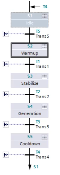
I implemented the operating logic so that the plant could move through startup, stabilization, power generation, cooldown, and fault handling in a structured sequence. This approach improved determinism in the PLC program and made system behaviour more transparent from both the programmer and operator perspective.
1. Warmup
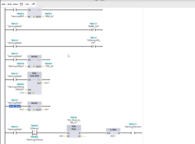
The sequence begins in Warmup after the operator issues a start command. In this mode, the rotor is allowed to turn at a controlled low speed while the oil pump runs at a low flow rate. The objective is to bring the system to a thermally ready condition before increasing load.
- Controlled low-speed rotor operation
- Low oil pump output for initial circulation
- Transition after oil temperature reaches operating threshold and remains stable
2. Stabilize
Once the machine is warmed up, the system transitions into Stabilize. In this phase, generation is ramped up in a controlled way until the target output is achieved. The logic checks that the process remains within the allowable operating band before allowing the next transition.
- Increase generation toward desired output
- Monitor process stability around target power
- Transition only after output remains within tolerance for a defined period
3. Generation
Generation is the normal running mode of the plant. In this state, the process is maintained at operating conditions and the station interlock is engaged so the plant can deliver output. The PLC continues to supervise all critical process variables and alarm conditions while maintaining stable operation.
- Normal production mode
- Station interlock closed
- Continuous monitoring of speed, flow, temperature, and generated power
4. Cooldown
When a stop command is issued, the system does not simply shut off. Instead, it enters a controlled Cooldown mode where the interlock is opened, rotor speed is reduced, and oil circulation is maintained until the system temperature falls below a safe limit.
- Controlled reduction of speed
- High oil flow maintained for equipment protection
- Transition to Idle only after temperature falls below threshold
5. Idle
Idle represents the safe non-running state of the plant. In this mode, the interlock is open, the baffle is de-energized, and the brake is engaged. This mode provides a stable resting condition until the next start request is issued.
- Safe resting state
- Brake engaged
- Interlock open and process outputs returned to non-running condition
6. Fault
Fault mode handles abnormal operating conditions such as overspeed, overcurrent, high oil temperature, oil flow faults, brake failure, or emergency stop events. In this state, the normal sequence is aborted and the system executes a protective response designed to place the plant into a safe condition.
- Sequence abort on abnormal conditions
- Protective actions applied automatically
- Operator alerted through alarms and fault indication
Structuring the project around these modes helped demonstrate more than just PLC programming. It showed how I think about automation systems in terms of process states, transition logic, operator visibility, and safe machine behaviour — which is exactly how industrial control systems are designed in practice.
PLC Implementation
The PLC implementation was developed in Siemens TIA Portal with a focus on structured logic, maintainability, and clear separation between sequence control, device control, alarm handling, and operator interaction. Rather than building the program as disconnected rungs, I treated it as an integrated industrial control system in which each part of the logic had a defined purpose within the overall plant behaviour.
I used Ladder Logic for core device control, permissives, interlocks, alarm handling, and discrete process actions, while Siemens GRAPH was used to implement the sequence-driven operating modes of the plant. This combination allowed the system to remain both readable and scalable: Ladder Logic handled the low-level execution and safety behaviour, while GRAPH provided a clean framework for startup, stabilization, generation, cooldown, and fault-related transitions.
Core PLC Work
- Implemented Ladder Logic for device commands, permissives, interlocks, and shutdown actions
- Built sequence-based control using Siemens GRAPH for mode transitions
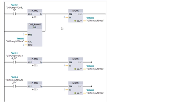
- Programmed HOA logic for manual, off, and automatic operation
- Created alarm logic with delay timers, inhibit conditions, and horn behaviour
- Integrated analog and digital I/O into one coordinated control strategy
Engineering Approach
- Structured logic for easier troubleshooting and readability
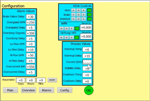
- Tag-based design to support HMI integration and configurable setpoints
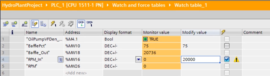
- Use of watch tables for commissioning, simulation, and debugging
- Clear separation between sequence logic, process logic, and alarm response
- Designed for deterministic and repeatable plant behaviour
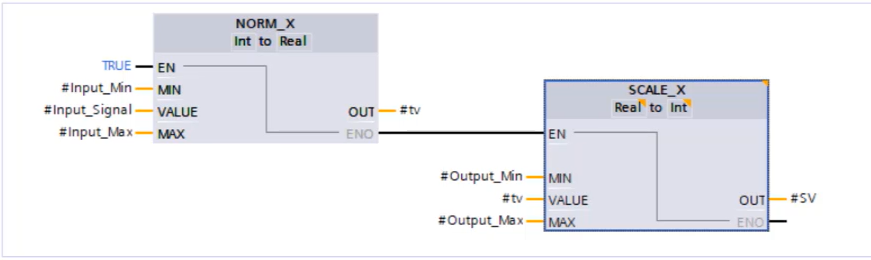
A major part of the implementation involved translating process requirements into practical PLC logic. This included handling analog signal scaling for field values such as rotor speed, oil flow, oil temperature, and generated power, while also generating output references for devices like the baffle actuator and oil pump VFD. Since the project brief defined both raw PLC ranges and engineering-unit display values, the logic had to correctly convert between machine-level signals and operator-facing process values.
I also implemented control features commonly seen in industrial automation projects, including HOA-based device control, alarm-driven shutdown actions, configurable setpoints and timers, sequence interlocks, and process monitoring structures that supported HMI visibility. In addition, watch tables were used extensively during testing to validate transitions, monitor internal tags, and troubleshoot behaviour under changing simulated process conditions.
From a controls engineering standpoint, this section of the project best represents the practical development work: building logic that is not only functional, but also organized in a way that supports commissioning, operator interaction, and future expansion. It reflects the kind of structured PLC programming approach used in real industrial automation environments.
Alarm and Safety Logic
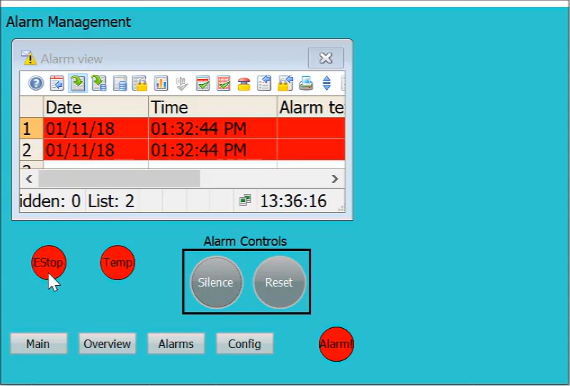
Alarm handling in this project was designed as both a protection feature and an operator workflow. Instead of using alarms only for indication, I built the logic so that abnormal process conditions were detected in the PLC, acted upon through defined safety responses, and then presented to the operator through the HMI for acknowledgement and reset.
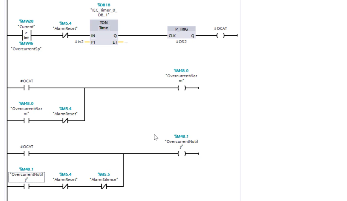
The PLC continuously monitored key fault conditions such as overcurrent, high oil temperature, overspeed, oil flow issues, brake failure, and emergency stop status. Depending on the alarm type, the logic applied either immediate response or timer-based delay logic before latching the alarm. Once active, the alarm could trigger protective actions such as disengaging the interlock, stopping the VFD, opening the baffle, engaging the brake, and activating the horn.
On the HMI side, the operator was given a dedicated alarm management screen to view active alarms, review alarm history, and interact with alarm controls such as silence and reset. The intended workflow was that the operator first identifies and corrects the root cause of the fault, then acknowledges or silences the alarm as needed, and finally performs a reset to clear the alarm state once the fault condition has been removed.
PLC Alarm Behaviour
- Detection of abnormal operating conditions
- Timer-based delay logic where required
- Alarm latching and notification bit generation
- Protective output actions tied to fault conditions
- Reset logic to clear alarms only after fault removal
Operator Alarm Workflow
- View active alarms and alarm history on the HMI
- Identify the faulted condition
- Correct the underlying process or equipment issue
- Use silence or acknowledgement controls as needed
- Reset the alarm after the condition is no longer present
This approach made the alarm system more realistic from an industrial automation perspective. It demonstrated not only how faults are detected in PLC logic, but also how operators interact with alarmed conditions in a controlled and structured way. That combination of PLC-side protection and HMI-side usability was an important part of making the project feel like a complete control system rather than only a simulation.
PID Control Strategy
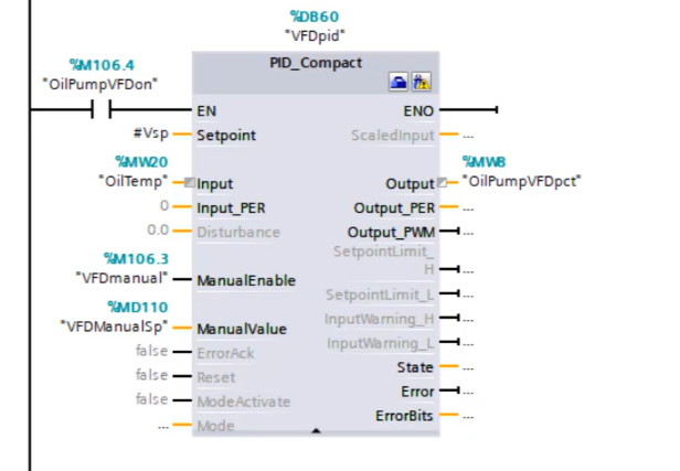
In addition to sequence logic and discrete control, I also implemented PID-based control for key analog process functions in the plant. This was used primarily for baffle control and oil pump VFD control, where the system needed to respond continuously to changing process conditions instead of relying only on fixed output commands.
The PID strategy helped make the plant behaviour more stable and more representative of a real industrial control system. For the baffle, PID control supported smoother adjustment of water flow to influence the process dynamically. For the oil pump VFD, PID control was used to regulate output more intelligently based on operating feedback, improving how the lubrication and cooling subsystem responded during plant operation.
Where PID Was Applied
- Baffle control for continuous process adjustment
- Oil pump VFD control for regulated output response
- Closed-loop behaviour using live feedback and setpoints
- Reduced dependence on abrupt manual output changes
Engineering Value
- Improved process stability under changing plant conditions
- Provided smoother actuator response
- Supported more realistic industrial control behaviour
- Strengthened practical experience with Siemens PID tools and tuning
The implementation was carried out using Siemens PID functionality inside TIA Portal, where the controller was integrated into the PLC logic and connected to live process values, setpoints, and output references. I also worked with PID tuning tools to observe controller response, compare setpoint versus measured input, and refine the behaviour of the loop for more stable operation.
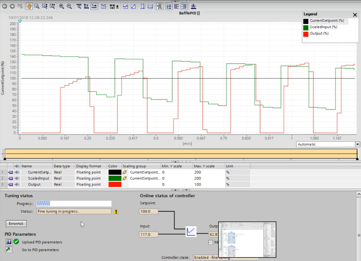
This part of the project helped demonstrate that my controls work was not limited to sequence logic and alarms alone. It also included closed-loop control concepts, tuning, and analog process regulation — all of which are important in real industrial automation systems.
Key Technical Skills Demonstrated
This project brought together multiple areas of industrial automation and controls engineering, from PLC programming and sequence design to HMI development, alarm handling, and commissioning-oriented testing. It reflects both technical implementation ability and practical engineering thinking.
PLC & Control
- Siemens TIA Portal
- Ladder Logic
- GRAPH sequence control
- PID control concepts
- Interlocks and permissives
HMI & Operations
- WinCC HMI development
- Alarm management
- Operator interface design
- HOA control strategy
- Process monitoring
Commissioning & Validation
- Analog I/O scaling
- Watch tables
- Testing and debugging
- Fault handling
- Structured troubleshooting
Overall, this project demonstrates my ability to design and implement an industrial-style automation system using Siemens tools, while also thinking through operator interaction, safety response, process behaviour, and maintainable PLC structure.